Software Documentation With UML Diagrams
Advantages of graphical software documentation and how to leverage UML diagrams in the development process
Unified Modeling Language (UML) diagrams provide a standardized graphical representation for software systems.
The overall software structure is the backbone of each system and has a significant impact on software quality and its maintainability. Any new feature or change needs to be integrated into this structure without interfering or breaking other existing parts of the system. Particularly in agile software development processes, it helps to keep the overall system structure well organized.
A standardized format like UML brings any developer of the project on the same page and simplifies feature discussions in the team.
Besides structural diagrams, UML is also used to describe behavioral aspects or interactions of a system to model the flow and data transitions.
Elements of UML Class Diagrams
A UML class diagram is a structural description of a software system. It represents a program on its class implementation level, which shows the properties and methods of each class. This representation provides a quick overview of the class and helps to identify common fields or methods that may be abstracted in a parent class or interface.

Furthermore, inheritance is depicted as relationships between the class entities in the form of differently styled connections.

These basic elements are sufficient to formalize a software architecture in a concise diagram that can be used as a reference during software development.
Challenges of UML Diagram Visualizations
There are many more types of UML diagrams beside the class diagram which document different aspects of the software. Activity diagrams e.g., describe individual workflows or sequence diagrams that incorporate a time sequence. All these diagrams have one thing in common: they want to represent connected elements.
The basic elements of a class diagram are the class entities with an arbitrary amount of stacked labels for the name of the class with its methods and properties and the connections that support different dash styles and arrows. Depending on the interactivity of the visualization, it also needs additional elements to add or remove fields and maybe collapse different sections on the class entities.
Another aspect that is even more important for the readability is the arrangement of the class entities and the paths of the relations. The dependency chain defines a structural order on the classes and interfaces and should be reflected in the graphical representation. To avoid confusion in the diagram, crossings of relationship paths should be minimized, and similar typed relationships may be bundled together.
Considering all of these aspects manually is very time consuming and often leads to unsatisfactory diagrams, which in the worst case can be even more confusing than helpful.
Utilizing a Sophisticated Visualization Solution
A comprehensive visualization solution needs to address all aspects of UML diagram visualization. It needs to be adjustable to the varying needs of the UML diagram rendering and creation.
yFiles is a commercial programming library explicitly designed for diagram visualization and is a perfect match for the challenges of UML diagram visualization. Its extensive customization options allow almost any visual representation of the UML diagram elements and any interactive user input. The sophisticated layout algorithms of yFiles can automatically arrange the entities in a concise and clear diagram.

Diagrams can be created from an existing code base, or interactively with intuitive keyboard, mouse, and touch gestures. The generic I/O mechanism of yFiles allows to store and create diagrams from the format that fits best the use case, e.g. JSON.
UML Diagram Editor Example
The UML Diagram Editor Sample Application that comes with yFiles for HTML implements these features and shows how the different challenges of UML class diagram visualization are addressed.
Interactive Class Entities
The application uses SVG styles to visualize the class entities which render the name, attributes, and methods. The built-in mechanism to place and render labels allows for stacking the labels easily and automatically clips the text with an optional ellipsis.
Clicks on a class entity are forwarded to the style implementation, which allows listening for clicks on interactive elements, e.g. to collapse the attributes or methods section, to select single labels on the class, and to add a new or remove the selected entry.
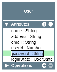
The class entities also support label editing. Double-clicking a label on the class entity opens up an input field with which that label can be edited.
Context-sensitive Interactions
Diagram editors are often cluttered with a complex and confusing user interface. This example tries to avoid unnecessary elements and instead uses context-sensitive interactions to help the user focus on a particular task.
Although yFiles for HTML comes with built-in support for creating new connections, in this application, it is modified to show a connection context menu when a class entity is selected.
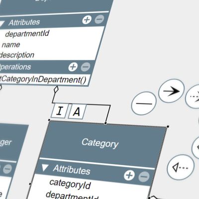
This context menu that is tailored towards a clean user interface is an intuitive way of helping the user to create new connections. Another further customization in the web application is that newly created connections automatically create a new class entity if the gesture ends on the empty canvas.
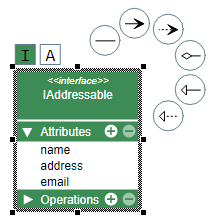
The context menu can also be used to adjust the class entity itself. In this example, it is used to switch between the different entity types, i.e. class, interface, or abstract.
Example Source Code
With yFiles, UML diagrams can be created on all supported platforms. yFiles for HTML, yFiles WPF, yFiles.NET, and yFiles for Java (Swing) come with a UML Diagram Editor Sample Application that demonstrates tailored visualizations for the nodes and connections, and a customized user interaction that eases working with the diagrams.
The source code of the UML Diagram Editor Sample Application is part of these yFiles packages and available on the yWorks GitHub repository:
Implement Your Own UML Diagram Editor
Test the yFiles diagramming library with a fully functional trial package. To implement your own UML diagram editor, start with the UML Diagram Editor Sample Application that is part of the yFiles package. It’s not only a showcase application but also provides best-practice source code that you can re-use in your own project.
yFiles makes it easy to customize all aspects of this application, for example include your own styling, change the user interaction, or load the data from your own data source. Features like the node visualizations and the specialized automatic layout are separate components that work in any yFiles-based project.
-
Download the trial version of yFiles for your target platform at the yWorks Customer Center.
-
Navigate to the source directory of the UML Diagram Editor Sample Application.
-
Explore the sample application’s features and
-
adjust its source code to match your requirements or
-
copy the source code of the features you like to your own project.
-